
Benoit Debled
Software DeveloperFirmware Developer
SysAdmin
Entrepreneur
Aquarium Light Project
When a problem occurs, I often like to think outside the box for a solution. I had a lot of issues with the lighting system that came with the fish tank. Instead of buying a new lighting system, I thought of a DIY project to make it even better. It is not very hard to make an unreiliable on/off solution better, but here is what I wanted for the new solution.
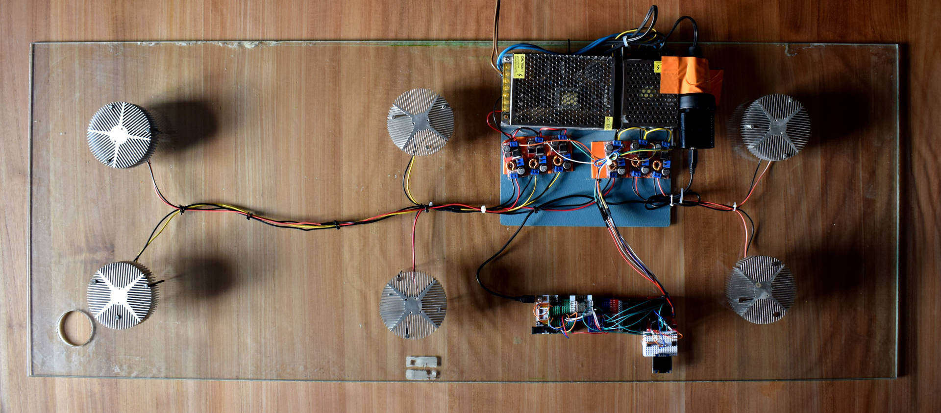
- The system had to be made out of 8 indivudally controllable LEDs
- The brightness of the LEDs can be set (Mode 1)
- There is a cloud mode (Mode 2): in this mode, the led's brightness will vary as if there were cloud going over the fish tank.
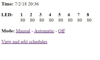
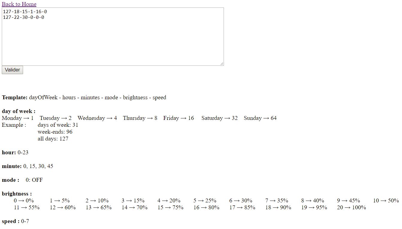
- There is a web interface that allows the following opperations: - Set the led to the desired mode - Display and set rules so that it is possible to change the mode according to the time of the day and the weekday it self. It is therefore possible to turn on the aquarium at a brightness of 80% every Sundays at 8pm.
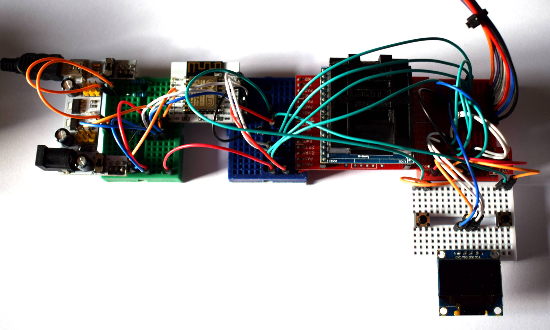
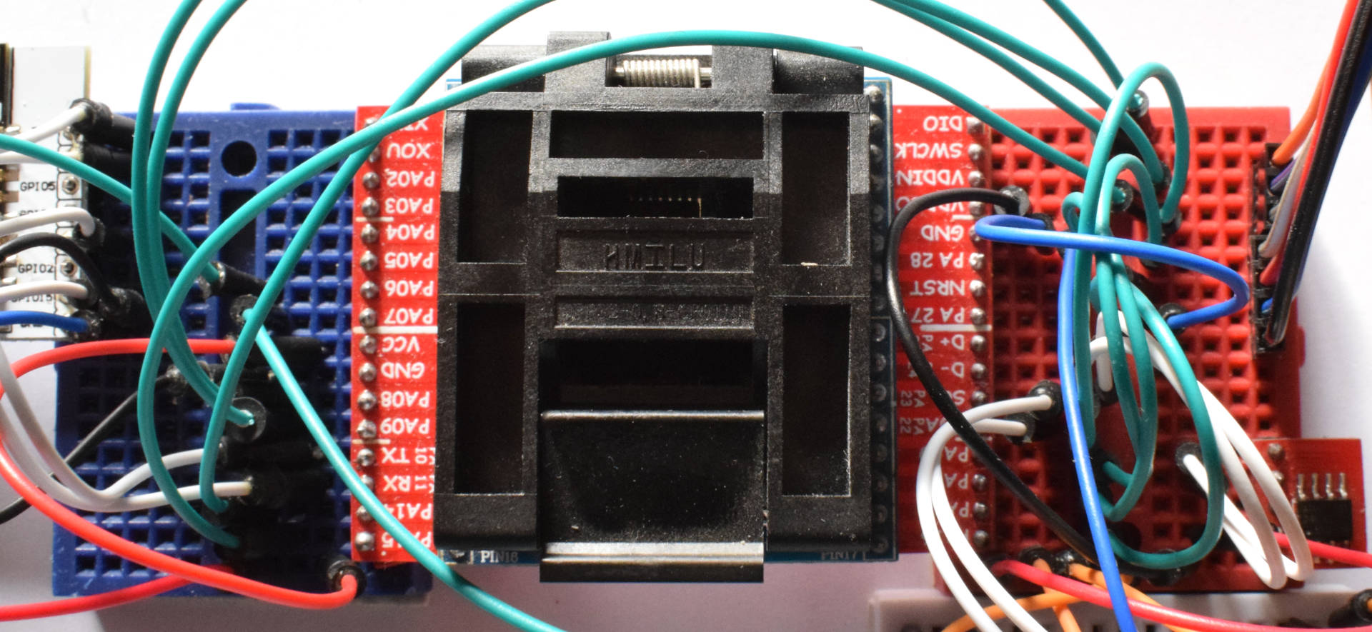
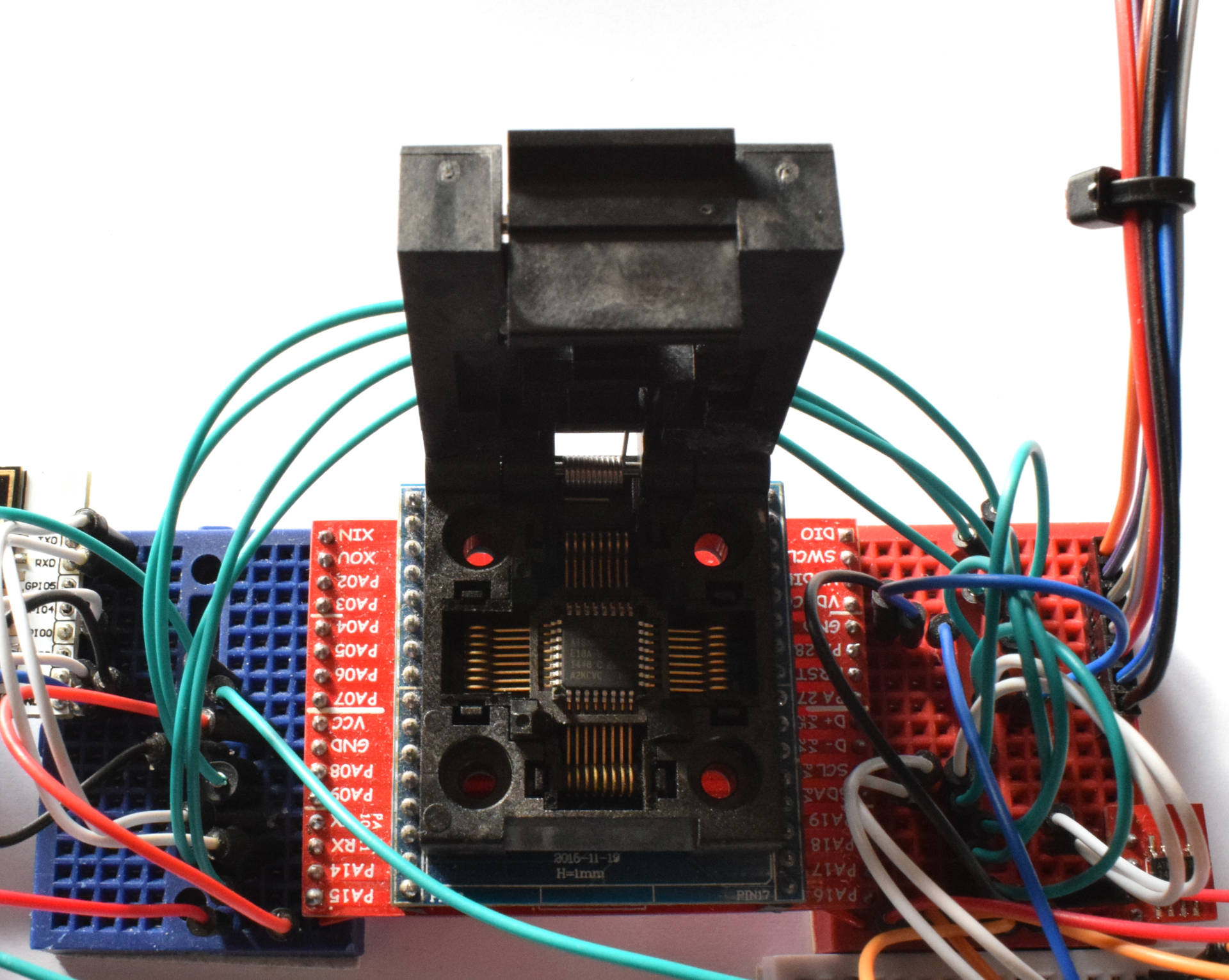
For this project, I used Arduino as it provided me a quick development solution. For the board, I "used" the Arduino Zero. I say "used" between parenthesis as I actually just used the microcontroller of that board, the ATMEL SAMD21G18A. Wait... Scratch that... I actually used the SAMD21E18A, notice the E instead of the G? That's just the number of pins of the chip. The G version (used in the arduino Zero board) has 48 pins whereas the E version has only 32 pins. As the 32 pins were enough for me, I used the E version. This doesn't change anything on the firmware side.
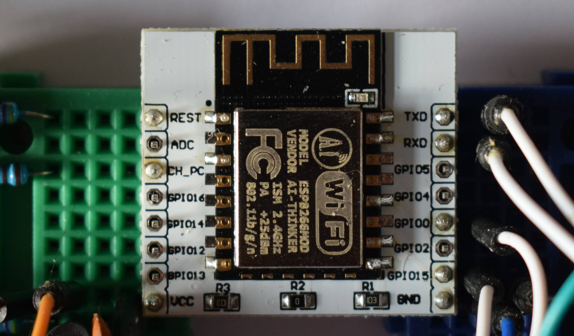
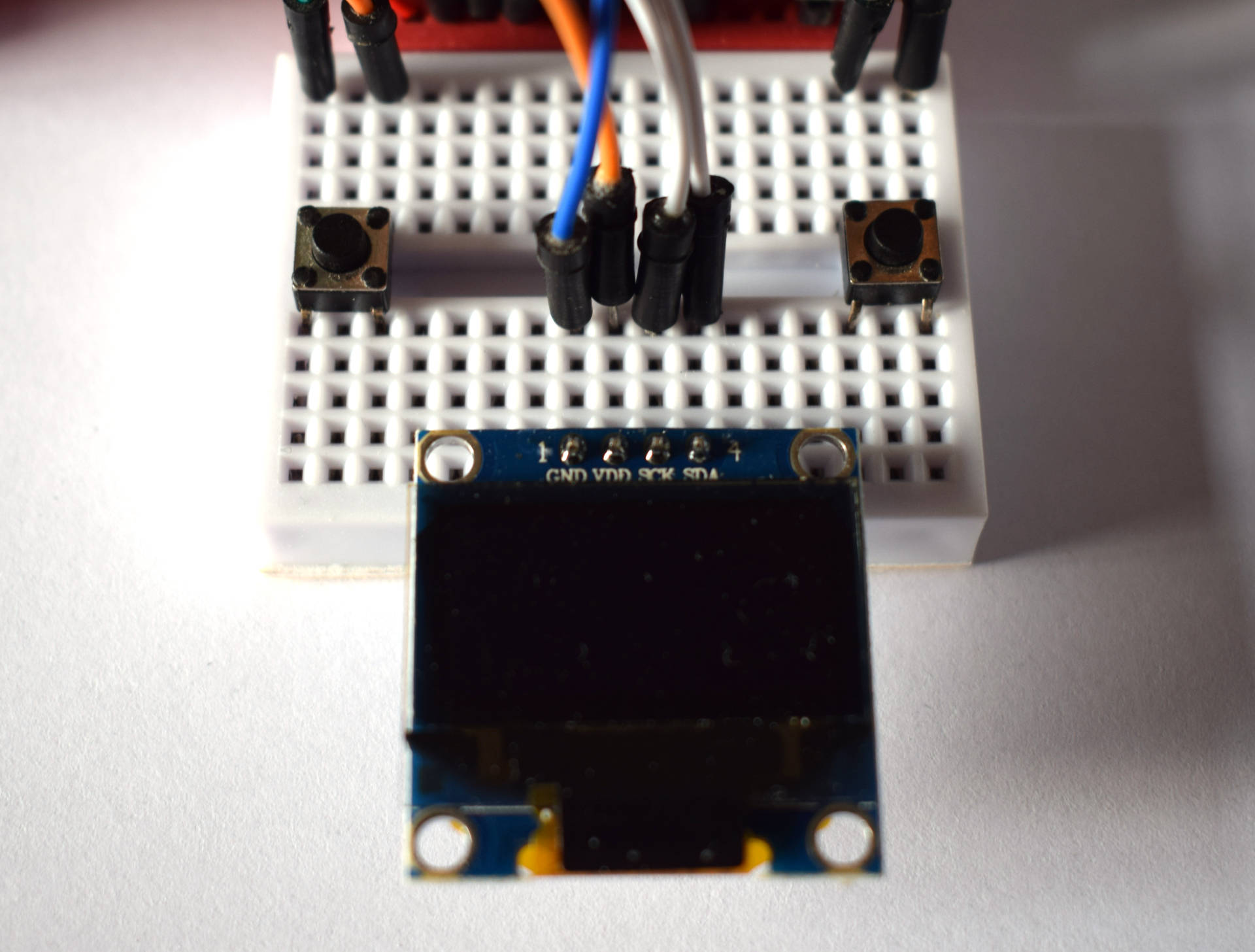
As for the external components, I used the ESP8266 for the WiFi and an 0.96" oled screen. Also, an eeprom memory chip has been used. The SAMD21 microcontroller family does not have an eeprom. Though it is possible to emulate one as it is possible to write on the flash of the microcontroller, it is a lot easier to use an external eeprom chip. The eeprom chip is the 24C32, yes, I know it is deprecated but that's the only one I had laying arround when doing this project. I actually had plenty, I just desoldered it of the well known DS1307 RTC module.
The code of this project is available on GitHub
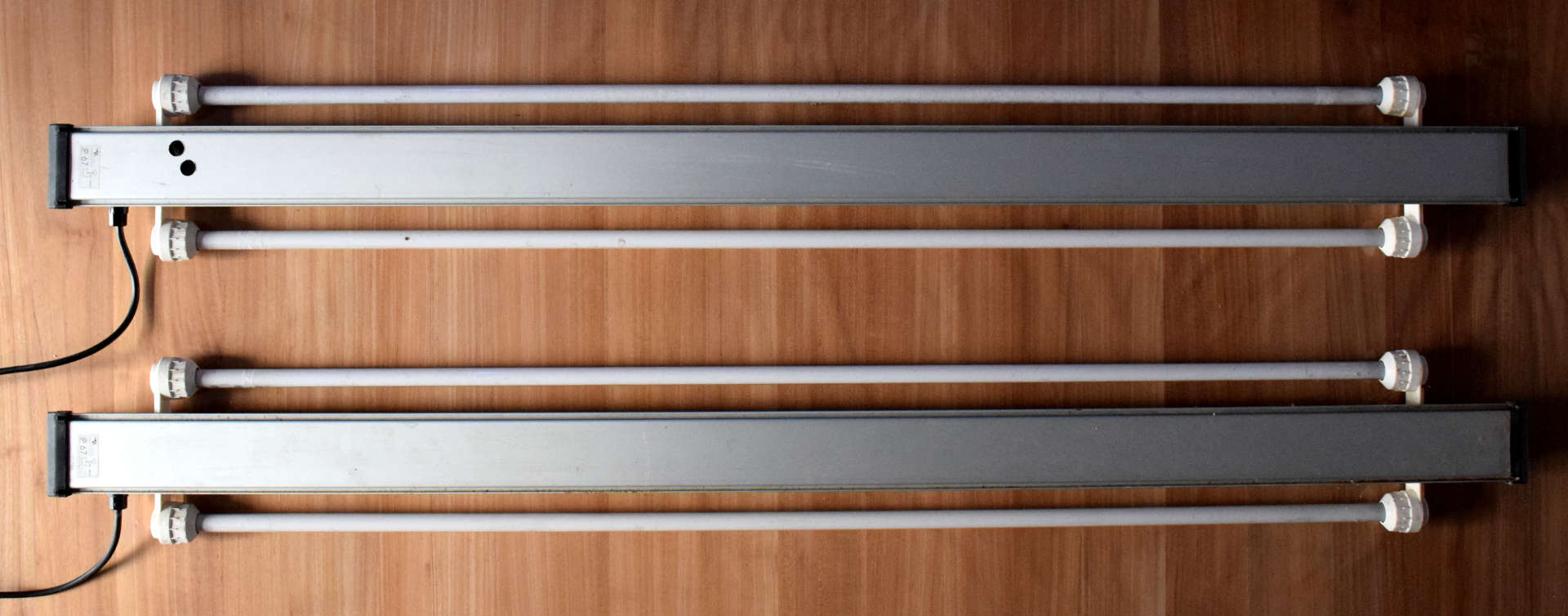
As the following pictures depicts, the old system consited of 4 neon tubes that came with the fish tank. The new one is made out of the 8 individually controllable LEDs.
What's next for this project?
A custom made PCB has been designed and printed in order to have a cleaner an more reliable solution. The PCB is unfortunatly sitting on a shelf waiting for me to have a little bit of time so I can solder and test everything.
The second thing that is still to be done is the development of the cloud mode.